Thursday, July 22, 2010

Digital System and Binary Numbers

Digital Systems:
I have got many emails from students regarding  Digital System and Binary Numbers conecpts so this is quick review what is Digital System and Binary Numbers? and what it does.....i think it will help u guys...if u guys really intersted and want to become logical designer Download this book Digital Design (4th Edition) only book that can tech u basics in professional way recommended by many designers...
 Digital systems are used in:
  1. Communication
  2. Business transaction
  3. Traffic Control
  4. Medical treatment
  5. Internet
The signals in digital systems use just two discrete values: a binary digit. Binary digit
called a bit, has two values: 0 or 1.
Example: The decimal digits a through 9 are represented in digital system with a code
of four bits (e.g. is represented by 0111, 8 is represented by 1000, 9 is represented by
1001).

Binary Numbers
  • Decimal number:
         The decimal number system is said to be of base, or radix, '10' because it uses 10 digits
          (0, 1, 2, 3, 4, 5, 6, 7, 8, 9).

Example:
The decimal number 245 may be written as
2x10²+4x101+5x100
where 2, 4, and 5 are the coefficients. 
  • Binary Number System: 
         The coefficients of the binary number have only two possible values: '0' or '1'.

Example:
(1001)2 its equivalent decimal number is : 1x23+0x22+0x21+1x20 = 8 + 0 + 0 + 1 = 9
where 1, 0, 0, and 1 are the coefficients. 
  • Octal number system (Base 8):
         The octal number system is said to be of base, or radix, '8' because it uses digits
   (00, 01, 02, 03, 04, 05, 06, 07, 10, 11, 12, 13, 14, 15, 16, 17). 
  • Hexadecimal number system (Base 16):
          It uses 16 digits : (0, 1, 2, 3, 4, 5, 6, 7, 8, 9, A, B, C, D, E, F). The letter A, B, C, D, E,
  and F are used for the digits 10,11, 12, 13, 14, and 15 respectively.

Example:
(124)16 = 1x162 + 2x161 + 4x160= 256 + 32 + 4 = 292


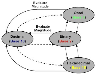
NUMBER BASE CONVERSION


Decimal to Binary conversion
  1. Divide the number with base '2'.
  2. Take the remainder 0 or 1 as a coefficient.
  3. Take the quotient and repeat the division.


Decimal to Octal conversion


Binary to Octal conversion

 Binary to Hexadecimal


Octal to Hexadecimal conversion


Complements:


The meaning of complement is something required to make a thing complete. For example, salsa complements tortilla chips, beer complements pizza, an ice cream cone complements a hot summer day, and apple sauce complements pork chops. A key concept to explore is how two things complement each other. For example, when a piece of pizza is removed from a whole pizza the piece complements what is left behind and vice versa. Each of the 4 following complements use the same concept except in different bases and what is considered a complete number in that base.

  • 1’s Complement: 
         The 1’s complement finds whatever is needed to make an entire set of 1’s. This is shown in the


  •  2’s ComplementFinding the 8 digit 2’s complement of 01101100
  • 9’s ComplementThe 9’s complement finds whatever is needed to make an entire set of 9’s. This is shown in the    
  • 10’s ComplementFinding the 5 digit 10’s complement of 1357 
      

Basic Logic Gate

         A logic gate performs a logical operation on one or more logic inputs and produces a single logic output. The logic normally performed is Boolean logic and is most commonly found in digital circuits. Logic gates are primarily implemented electronically using diodes or transistors, but can also be constructed using electromagnetic relays (relay logic), fluidic logic, pneumatic logic, optics, molecules, or even mechanical elements.

       In electronic logic, a logic level is represented by a voltage or current, (which depends on the type of electronic logic in use). Each logic gate requires power so that it can source and sink currents to achieve the correct output voltage. In a pure logic diagram logic levels and power supply connections do not exist and are not shown, but in a full logic circuit diagram, documenting the implementation of the logic, these are required.


      All other types of Boolean logic gates (i.e., AND, OR, NOT, XOR, XNOR) can be created from a suitable network of NAND gates. Similarly all gates can be created from a network of NOR gates. Historically, NAND gates were easier to construct from MOS technology and thus NAND gates served as the first pillar of Boolean logic in electronic computation.


     Truth table is a table that describes the behaviour of a logic gate or any combination of logic gates. It lists the value of the output for every possible combination of the inputs and can be used to simplify the number of logic gates and level of nesting in an electronic circuit. In general the truth table does not lead to an efficient implementation; a minimization procedure, using Karnaugh maps, the Quine–McCluskey algorithm or an heuristic algorithm is required for reducing the circuit complexity.

Truth table & Symbols


Friday, July 2, 2010

32x8 FIFO

FIFO is nothing but simple queue like we standing in cinema theaters.one who standing first will get ticket last guy may or may not...this is concept.in technical 32x8 fifo is 32 locations with each location can accommodate 8 bit data...in this writeptr and readptr plays very important role...operation starts when write enables data stores into reg and startes incriment writeptr..after completion write operation we have to enable read operation..when read is enabled readptr starts incrimenting and extract data from register....

module fifo2 (dout,enb1, wrtenb, redenb, clk, rst, out,wrtptr,redptr, empty,full);
input enb1;
input [7:0] dout;
input wrtenb;
input redenb;
input clk;
input rst;   
output [4:0] wrtptr;
output [4:0] redptr;
output [7:0] out;
output full;
output empty;
reg [7:0] out;
wire full;
wire empty;
reg [7:0] dreg [0:31] ;
reg [4:0] wrtptr;
reg [4:0] redptr;
always@(posedge clk or negedge rst)
    begin
        if(~rst)
            begin   
            wrtptr<=5'b00000;
            redptr<=5'b00000;
           
            end   
        else  if(enb1)
            if(wrtptr==5'b11111)
                begin
                    wrtptr<=5'b00000;
                   
                end
           
         if(wrtenb==1&&redenb==0)
           
                begin
                   
                     dreg[wrtptr]<=dout;
                    wrtptr<=wrtptr+1;
                end
                if(redptr==5'b11111)
                    begin
                        redptr<=5'b00000;
                       
                        end
                   
              if(wrtenb==0&& redenb==1)
                    begin
                   out <=dreg[redptr];
                  redptr<=redptr+1;
               
                end
            end
       
            assign  full=(wrtptr==5'b11111)?1'b1:1'b0;
            assign empty=(redptr==5'b11111)?1'b1:1'b0;
       endmodule
You could download file 32x8fifo.v and testbench.tb here

Thursday, July 1, 2010

3x8 Decoder

A decoder is a device which does the reverse operation of an encoder, undoing the encoding so that the original information can be retrieved. A slightly more complex decoder would be the n-to-2n type binary decoders. These type of decoders are combinational circuits that convert binary information from 'n' coded inputs to a maximum of 2n unique outputs. We say a maximum of 2n outputs because in case the 'n' bit coded information has unused bit combinations, the decoder may have less than 2n outputs. We can have 2-to-4 decoder, 3-to-8 decoder or 4-to-16 decoder. We can form a 3-to-8 decoder from two 2-to-4 decoders (with enable signals).


module dec (x, z);
input [2:0] x;
output [7:0] z;
reg [7:0] z;
always @ (x)
    begin
            case(x)
                3'b000 : z=8'b00000001;
                3'b001 : z=8'b00000010;
                3'b010 : z=8'b00000100;
                3'b011 : z=8'b00001000;
                3'b100 : z=8'b00010000;
                3'b101 : z=8'b00100000;
                3'b110 : z=8'b01000000;
                3'b111 : z=8'b10000000;
                default:z=8'bxxxxxxxx;
            endcase
                    end
endmodule

You could download file dec.v and testbench.tb here

Wednesday, June 30, 2010

8x1 Multiplexer

It is an combinational device that performs multiplexing; it selects one of many analog or digital input signals and forwards the selected input into a single line. A multiplexer of 2n inputs has n select lines, which are used to select which input line to send to the output.it just acts as switch between devices.....

module mux (s, z, x);
input [2:0] s;
output z;
input [7:0] x;
reg  z;
always @(*)
    begin
        case(s)
            3'b000 :z=x[0];
            3'b001 :z=x[1];
            3'b010 :z=x[2];
            3'b011 :z=x[3];
            3'b100 :z=x[4];
            3'b101 :z=x[5];
            3'b110 :z=x[6];
            3'b111 :z=x[7];
            default: z=1'bz;
        endcase
        end
 endmodule
You could download file mux.v and testbench.tb here

Tuesday, June 29, 2010

JK Flip-Flop

The JK flip-flop augments the behavior of the SR flip-flop (J=Set, K=Reset) by interpreting the S = R = 1 condition as a "flip" or toggle command. Specifically, the combination J = 1, K = 0 is a command to set the flip-flop; the combination J = 0, K = 1 is a command to reset the flip-flop; and the combination J = K = 1 is a command to toggle the flip-flop, i.e., change its output to the logical complement of its current value. Setting J = K = 0 does NOT result in a D flip-flop, but rather, will hold the current state. To synthesize a D flip-flop, simply set K equal to the complement of J. The JK flip-flop is therefore a universal flip-flop, because it can be configured to work as an SR flip-flop, a D flip-flop, or a T flip-flop.

module jkff (j, k, clk, reset, q);
input j;
input k;
input clk;
input reset;
output q;
reg q;
always@(posedge clk or negedge reset)
    begin
    if(~reset)
        begin
            q=1'b0;
        end
    else if(j==1'b0 && k==1'b1)
        begin
            q=1'b0;
        end
     if(j==1'b1 & k==1'b0)
        begin
            q=1'b1;
        end
     if(j==1'b1 & k==1'b1)
        begin
            q=~q;
        end
     if(j==1'b0 & k==1'b0)
        begin
            q=q;
            end
        end
endmodule 
You could download file jkff.v and testbench.tb here.

D Flip-Flop

The D flip-flop is the most common flip-flop in use today. It is better known as delay flip-flop (as its output Q looks like a delay of input D) or data latch.The Q output takes on the state of the D input at the moment of a positive edge at the clock pin (or negative edge if the clock input is active low).The D flip-flop can be interpreted as a primitive memory cell.

module dff (data, clk, reset, q);
input data;
input clk;
input reset;
output q;
reg q;
always@(posedge clk)
begin
if(~reset)
begin
q<=1'b0;
end
else
begin
q<=data;
end   
end
endmodule
You could download file dff.v and testbench.tb here.